3D spacing systems
Automatic 3D spacing system for water jet cutting
The distance between workpiece and cutting nozzle during water jet cutting is a significant aspect for the quality of the cut and the parts tolerance.
Machining 3D contours has shown that the workpiece to be cut often does not match the 3D CAD data. Production tolerances and also welding seams can result in collision of the cutting head with the workpiece, or the correct distance between nozzle and workpiece is not maintained. Up to now, the deviations had to be taken into account in the 3D programming system or the workpiece has been realigned.
In order to shorten these often time-intensive work processes, a 3D spacing system has been developed where the cutting nozzle automatically follows the material.
Functional principle:
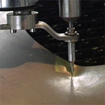
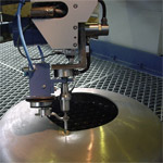
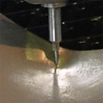
A special measuring sensor is mounted on the cutting head instead of the cutting nozzle. The 3D program created by CAD/CAM is started in the “Measurement run” operational mode. The measuring sensor scans the 3D contour using previously defined parameters and thus records the deviation between actual and target dimension. After the measuring run, the 3D program is analysed with software developed by H.G. Ridder Automatisierungs GmbH and the measurement differences are inserted as correction value. It goes without saying that the correction is always made in the water jet direction so that the cutting contour is maintained.
 The measuring sensor is replaced by the cutting nozzle in order to be able to cut the 3D part. Using the new, generated parts program, the correct distance between nozzle and workpiece is achieved at every place for the water jet cutting.
As well as the 3D correction, the 3D scanner can also be used as a TeachIn System for 2.5D/3D programs. The contour to be cut is moved along using the scanner and the axis positions for all axes involved are saved automatically. At the end of the TeachIn process, the recorded control points are connected with predefined splines.


